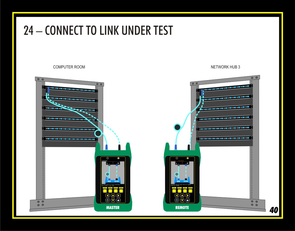
Bring the units to opposite ends of the link, according to the position specified during the Link Name procedure. For this demonstration, the MASTER goes to the COMPUTER ROOM and the REMOTE goes to the NETWORK HUB 3.
Connect into the first fiber pair, which would typically be Fibers 1 and 2 in the patch panel. You will see that the fiber name – FIBER#1&2 – appears at the top of the screen on both units.
Based on the chosen settings, the fiber cables should be connected straight in – the MM cable goes to the left hand port and the OPM cable goes to the right hand port.
Press any key on the meter to begin testing the fiber pair.
During the test, the screens will show feedback related to the units communicating with each other.

