
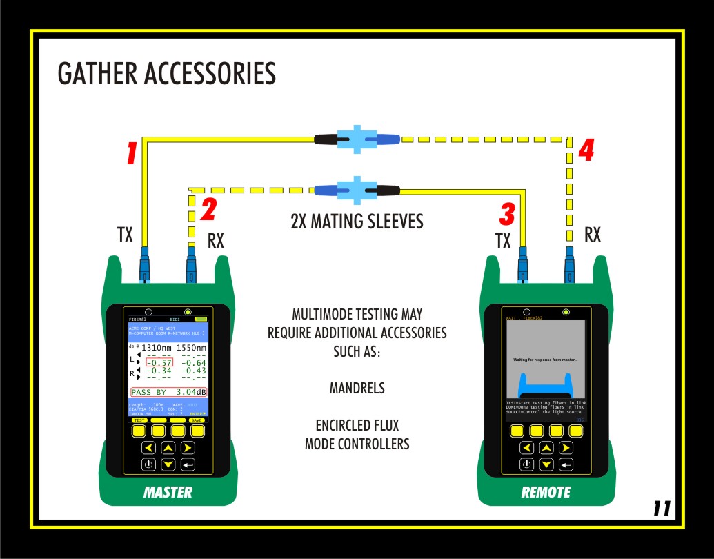
Only two of the cables will be used at first for setting the 1-jumper reference. These are the light source cables marked as 1 & 3 in the diagram.
The power meter test cables, marked as 2 & 4, come into play only when the fiber link is being tested.
However, it is a good idea to make sure all the test cables are working together properly before testing.
PAIR MODE includes a step that allows the user to check all 4 cables together, but this step requires two mating sleeves to bring all the cables together. This diagram shows how the cables are attached during this step.
Lastly, testing multimode fibers may require additional accessories such as fiber optic mandrels, or special reference cables called Encircled Flux mode controllers. Ensure that you are using the correct accessories when testing multimode fibers.