
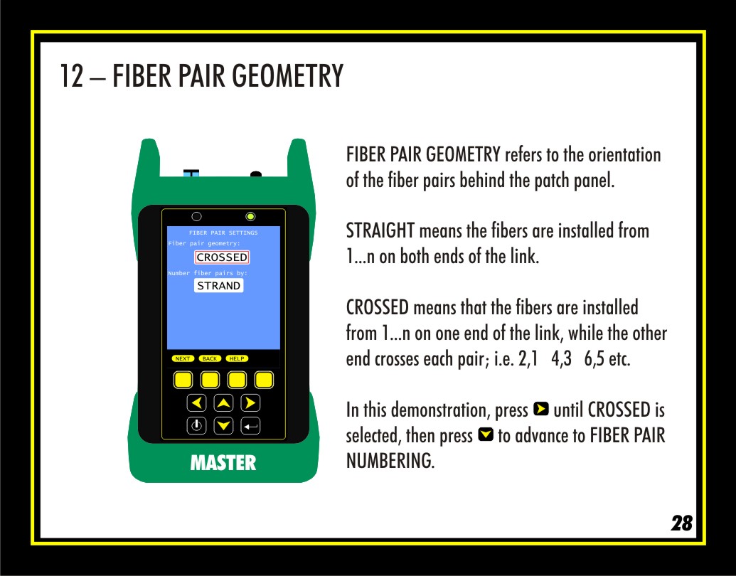
FIBER PAIR GEOMETRY refers to the orientation of the fibers as they are installed behind the patch panels. There are two options:
STRAIGHT is where the fibers are installed 1....n from left to right on both ends of the link.
CROSSED is where the fibers are installed 1....n from left to right on one end of the link, while the other end crosses each pair from left to right; i.e. 2,1 4,3 6,5 etc.
This setting is important because it tells the MASTER and REMOTE units which diagram to show during testing. These diagrams show the user how to connect the patch cables into the link under test.
In this demonstration, press the right arrow until the setting shows CROSSED, then press the down arrow to highlight “Number fiber pairs by”.
The CROSSED setting will display diagrams on both the MASTER and REMOTE that prompt the user to connect the test cords straight in to the fiber pairs. This will become apparent later on in the slideshow.