
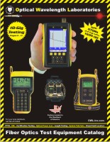
| Video #: C1001 | Duration: 14:17 | File Size: 367.7 MB | File Type: MP4 |
|
Description: Basic information
about the concepts surrounding the testing of fiber
optic links, including: --understanding the value of being well-versed in fiber optics knowledge; --understanding why testing optical fibers is so important; --understanding the different levels of testing an optical fiber; --being able to discern which types of test are valid, and which ones are not valid; --understanding the basic components and configuration of a properly designed fiber link; --understanding the basic procedure for properly testing a fiber link; and --being able to determine if a link is good or not. |
|||
|
Pause the video after each objective to answer the review questions below. |
|||
|
OBJECTIVE 1: UNDERSTAND THE VALUE OF BEING WELL-VERSED IN FIBER OPTICS KNOWLEDGE Datacom, Telecom, Video Distribution
Energy, Aerospace, Medical
Recognize emerging FO technologies/trends; know when the new tech will add value to a company's products/services; understand how the tech is implemented
OBJECTIVE 2: UNDERSTAND WHY TESTING OPTICAL FIBERS IS SO IMPORTANT So that if active equipment does not communicate, it is not the fault of the fiber.
Sufficient safety margin ensures that a link will stay up and running even when slight problems occur
Health and Life Safety
OBJECTIVE 3: UNDERSTAND THE DIFFERENT LEVELS OF TESTING AN OPTICAL FIBER Testing vs. Measurement
A "test" looks for the presence of something, while "measurement" measures how much of that something you have
OBJECTIVE 4: DISCERN WHICH TYPE OF TESTS ARE VALID AND WHICH ONES ARE NOT VALID Test
Optical power
Flashlight, visual fault locator, go/no-go, qualification
optical power, optical loss, fiber link certification
Application and Generic
OBJECTIVE 5: UNDERSTAND THE BASIC COMPONENTS AND CONFIGURATION OF A PROPERLY DESIGNED FIBER LINK Optical fiber, inter-connections, and splices
Mating sleeve, bulkhead, adapter, coupler
Fusion and mechanical
Connections are temporary; splices are permanent
False. Patch panels prevent fragile installed fibers from being directly connected to active equipment.
OBJECTIVE 6: UNDERSTAND THE BASIC PROCEDURE FOR PROPERLY TESTING A FIBER LINK Power meter and light source
True
The measured light is dimmer than a separate baseline power level.
Positive. If -20 dBm is the optical reference, and the power measured through the link is -24 dBm, then the link has "dropped" (aka lost) 4 dB.
OBJECTIVE 7: DETERMINE IF A LINK IS "GOOD OR NOT" Loss measurement is compared to a "link budget". If the loss exceeds the budget, the link fails (not good). Likewise if the loss is within the budget, the link passes (good).
Add together optical fiber loss (dB per kilometer) + connection loss (dB per connection) + splice loss (dB per splice).
Use a cabling standard. Cabling standards are based on pre-defined loss parameters.
TIA, ISO, IEEE
TIA
|
|||
 |
 |
| All prices on this website are shown in US Dollars (USD) |