
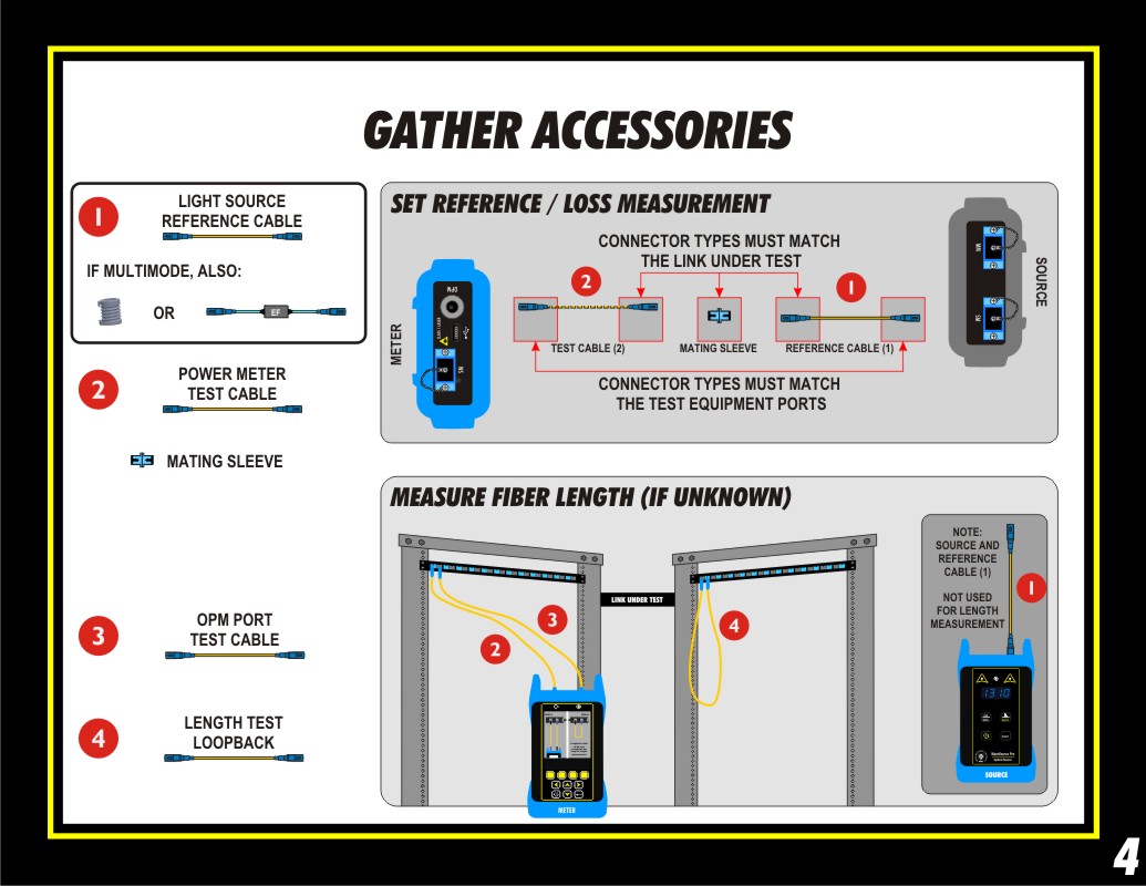
The next step is to gather the necessary accessories to perform the test.
NOTE: This step assumes that the link is installed with patch panels on both ends, which allows the user to use the recommended 1-jumper reference method. Other link configurations and reference methods will require the user to modify their test procedure accordingly.
First, the patch cables must be the same fiber type as the link under test. If the fiber length is already known, you will need 2 test cables. If you need the meter to measure the length, you will need 4 test cables.
Cable # 1 (i.e. light source reference cable): look at light source port, then look at patch panel. This will determine the configuration of the light source reference cable, as well as what universal adapter to install on the Fiber OWL 7. If LC or other 1.25mm ferrule connector is used, install the 1.25mm cap. However if 2.5mm ferrule connectors, such as SC, ST, or FC are installed in the patch panel, install the 2.5mm cap.
If the fiber type is multimode, then you will also need to wrap the light source reference cable around an appropriately-sized fiber optic mandrel.
If the test requires encircled flux compliance, then an encircled flux mode controller will be used in lieu of the light source reference cable and mandrel.
Cable # 2 (i.e. power meter test cable): look at patch panel, then look at the universal cap. This will determine the configuration of the power meter test cable.
Cable # 3 (used to connect the meter's length test port to the link): look at the length test port, then look at the patch panel. This will determine the configuration of the power meter length test cable.
Cable # 4 (used as the loopback cable if length is being measured): both ends of the patch cable must match the link under test.
You will also need a mating sleeve (aka coupler, adapter, bulkhead, etc.) that has the same connector type as the link under test.